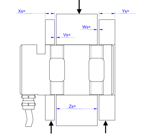
Force transmission

A description of the mounting situation is given on the second page of every data sheet. The way in which the loadpin should be loaded is described in this schematic representation.The supplied loadpin has been calibrated in exactly this configuration. No other load can change the calibration or lead to damage to or the destruction of the load pin
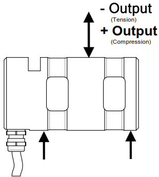
Output arrow
The output arrow indicates the direction in which the loadpin emits a positive signal.

Reversal of the output signal
| Output signal | Possibility of signal inversion |
|---|---|
| Passive signal (mV/V) | Exchange +Us and -Us |
| Voltage output (±10V) | With galvanically isolated inputs, GNDA and Ua can be exchanged. |
| Current signal (4..20mA) | No change of direction is possible |
If the direction of force deviates from the prescribed direction, measuring distortions will occur and the loadpin could be destroyed.

