All Products
Standard loadpins
Biaxial loadpins
Single-sided loadpins
Redundant loadpins
shackle loadpins
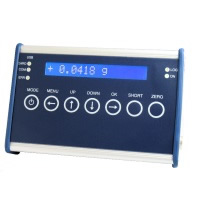
display loadpins
force measuring frame
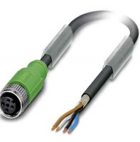
accessories
GBA – Loadpins
CBA – loadpins
Delivery time: (working days)